
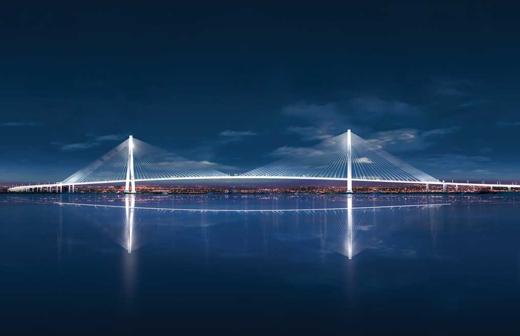
Photo: Gordie Howe International Bridge project
One of the busiest crossings in North America, the privately-owned Ambassador Bridge that spans the Detroit River between Windsor, Ont., and Detroit, Mich., is more than 90 years old and often a bottleneck for car and commercial truck traffic. In 2015, after more than 15 years of studies, hundreds of community and stakeholder meetings and layers of governmental approvals, the Canadian Government, through its Crown corporation, the Windsor-Detroit Bridge Authority (WDBA), began to prepare the sites of the Canadian and U.S. ports of entry for the work to be undertaken by a private-sector partner. On the Canadian side, that included construction of a perimeter access road, relocation of utilities as well as filling, grading and drainage activities. On the U.S. side, work included significant utility relocation. Through its Michigan State partner, the Michigan Department of Transportation, WDBA began to acquire the properties on the U.S. side of the project for the new international bridge crossing between the two countries, to be jointly owned by Canada and Michigan, and paid for entirely by Canada.
In 2018, under a P3 agreement, Bridging North America (BNA) Constructors Canada GP joint venture (JV) won the $5.7 billion fixed-price contract to design, build, finance, operate and maintain the publicly-owned facilities for 30 years. Comprising Aecon, Fluor and ACS Infrastructure (the parent company of constructors Dragados-Canada and Dragados-USA), the JV began construction that October on the project’s four components: the bridge itself, the Canadian entry point and customs plazas, the U.S. entry point and the Michigan interchange linking the bridge to Interstate 75.
Scheduled to open in late 2024 for truck traffic, the 2.5-kilometre-long Gordie Howe International Bridge, named to honour the beloved Detroit Redwing, one of hockey’s all-time greats, will be among the five longest bridges in North America, and built to accommodate three Canadian-bound and three U.S.-bound lanes for cars and commercial traffic, and a dedicated multi-use path for pedestrians and cyclists. The Windsor port of entry will be the largest along the Canada-U.S. border, and the U.S. port of entry one of North America’s largest.
North America’s longest cable-stayed main span
Stringent environmental studies on both sides influenced the location of all four components of the P3 project, says Mark Butler, BNA’s director of communications. Most importantly, environmental concerns helped dictate the choice of the cable-stayed design, he says, since building the towers in the water might have impacted boat navigation, fish migration and water quality, and only a suspension or cable-stayed bridge could have been built for such a long span. In fact, at 853 metres across the Detroit River, the main span will be the longest of any cable-stayed bridge in North America. Further, at 227 metres, the two bridge towers will rival the tallest tower in Detroit’s downtown, the GM Renaissance Center.
The two main towers, from which the cables extend to support the bridge deck, each rise from the ground on two wishbone-shaped footings, before ascending as spires. Each of the tower footings require six piles, three metres in diameter, and three pairs of side span piers to transfer main span loads from the backstay cables to the ground. BNA subcontracted GFL Infrastructure for the foundation work on the Canadian side. Malcolm Drilling was the foundation subcontractor on the U.S. side.

“The requirements for this project’s longevity were a minimum of 125 years, so every little bit of it needed to undergo a massive amount of scrutiny,” said Justin Beaveridge, Dragados-Canada’s tower/foundations engineer. “As part of the contractual requirements, every major piece of work on the Gordie Howe Bridge had to have a full-scale model of that element performed ahead of time to prove we were competent and could execute the means and methods as described on paper.” Proving requirements included a three-metre full-depth test drill shaft, mock-ups of the footing, the side span towers, the tie beam and the post-tensioning and tower mock-ups, which were “the equivalent of a full four metre lift of the tower, complete with all rebar, formwork and accessories.”
For their test, Malcolm drilled a shaft three metres in diameter, “One hundred feet down to top of rock, with a 15-foot-deep rock socket,” identical to one that would be built to support the actual tower, said Jim Glider, Malcolm project manager. Then, to prove the capacity of both the pile and the bedrock, an O-Cell test was performed: a rebar cage, equipped at the bottom with an O-Cell – a hydraulically driven, high capacity, sacrificial loading device – was set into the shaft and concreted; once the concrete cured to an appropriate strength, the O-Cell was hydraulically pressurized to put a measurable load on the shaft in both an upwards and downward direction.
“This applied load determines the movement of the shaft under the prescribed amount of load,” Glider said. “The shaft resisted an equivalent top load of over 38 million pounds with only millimetres of movement.”

Coping with deadly gas and extreme artesian pressure
The limestone rock formation on both sides of the river contained hydrogen sulfide, an extremely deadly gas. The crews on both sides used H2S gas detectors when working at the top of the shafts and casings since “as we drilled into rock, we ran the risk of it coming up into the shaft,” said Glider. When these monitors went off a couple of times on the U.S. side, “we had to evacuate the site and follow our safety procedures to get back onto the site and to the hole.”
The foundation subcontractors on both sides of the Detroit River also had to deal with the challenge posed by water in the drilled shafts. Due to the geological formation found there, the groundwater is under strong artesian pressure. Such pressure occurs when the elevation from which an aquifer’s recharging water comes is higher than the elevation of the site’s groundwater because that water is confined underground by an overlying impervious layer of rock. When a shaft is drilled through this layer, the pressure caused by the “upstream” water in the aquifer causes the water in the shaft to rise above the level at which it is first encountered at the site.
However, despite the similar conditions, the Canadian and American subcontractors used very different installation techniques for their piles. On the Canadian side, GFL drilled the shafts in a traditional manner, says Beaveridge, approximately 30 metres down through overburden and then about 4.8 metres further into the bedrock.
“Pump the concrete too quickly and the tremie hose is going to want to push itself out of the concrete, which can be a huge issue.”
– Justin Beaveridge, Dragados-Canada
“To combat the artesian pressure, you need to prepare water to pour into the shaft as you’re vibrating the sections of liner down and drilling,” he said. “We had several shafts on the go at any given time and each required about 350 cubic metres of water. The maximum artesian water pressure we’d encounter was approximately three metres above the ground we were working on, so to prevent any blow-ins within the [drilled] shaft itself, we always had five metres of extra pipe and water above ground level to maintain positive pressure within the shaft.” To ensure that the water pressure from below didn’t bring “dirty” artesian ground water into the drilled shaft before the casing was sealed to the bedrock, the water pressure also had to be maintained above the soil plug, “in the bottom of the giant steel cylinder we’re vibrating into the ground.”
“GFL used a Watson 3110 – a very small drill – to start a two- or three-metre pilot hole, just enough to allow us to lift the steel liners,” which were 5.5- to 8.5-metre sections of 19-millimetre-thick, 3.143-metre-diameter spiral steel piles, said Beaveridge. “The first couple of metres were critical to ensure both the horizontal position and the verticality of the liner. They’d pick up the steel liner with the King Kong (APE Model 400) vibrator hooked up to one of their cranes, drop it into the pre-drilled hole and vibrate the liner into the ground with little or no drilling.”
Then the crew would pick up the second pipe section using the clamps on the vibrator, place it carefully atop the section of casing already in the ground, position it with help from the backing plate and begin Complete-Joint-Penetration (CJP) welding the joint to ensure water-tightness and full structural integrity of the casing “so that it’d stay in good shape and not crumple when we were vibrating the pile,” he said. When approximately a metre of that section remained out of the ground, the third section would be placed, CJP-welded and then vibrated down and seated into the bedrock, “with seven to eight metres of stick up so that there would be at least five metres of water head above ground level.”

“Most of the time we were using a Bauer BG 45, eventually upgrading to a BG 50. At that point we’d auger down, remove the material, all the while maintaining the water level in the shaft.”
Elevations had first been ascertained in the early works by boreholes; now, as the tool approached theoretical bedrock, the force on the auger and progress rates were more closely followed. “Once cuttings started being noticed on the tools, the geotechnical designer and consultant, Thurber Engineering, verified the consistency of bedrock across all the teeth on the tool,” said Beaveridge. If there was uncertainty, further excavation was required until all parties were satisfied that the true bedrock elevation had been determined. At that point we had to continue vibrating to ensure a target of 100 to 200 millimetres of embedment of the casing; to seal the liner against the bedrock and prevent any soil from entering the shaft during the works,” and to ensure the positive water head in the casing could be maintained.”
“Working in two shifts 20 hours a day, six days a week, we could get a liner down to the bedrock within 48 hours of commencement,” he said, and an average of about half a metre per 10-hour shift for the rock sockets, which were drilled using core barrels of different sizes and increasingly larger augers.
Once the drilling was finished, shafts had to be fully cleaned. For this, GFL rigged a tremie pipe about six inches in diameter with a larger ring that fit around the outside of the pipe, with teeth along the bottom that prevented the end of the tube from hitting the bottom of the shaft. This was attached to an air hose from a compressor along the outside of the tremie pipe. A crane lifted this device and dropped it to the bottom of the drilled shaft.
“We’d poured in some flocculent and let that settle overnight, then the air from the compressor would cavitate the water at the bottom, causing all the sediment to be thrown up the tube – essentially a giant vacuum,” Beaveridge said. Only when the pH and contaminant levels were within regulation limits could the water be put into on-site sedimentation ponds.
Once drilled, the shafts required stringent airlifting
“The airlifting was a very stringent requirement,” said Beaveridge. “We couldn’t have more than 12.7 millimetres of sediment along the bottom of the three-metre-diameter shaft, on average, no more than seven millimetres, measured by means of the SQUID [Shaft Quantitative Inspection Device] test.” Once cleaned, the cylindrical rebar cages were dropped in and concreted.
Balancing the height of the hose while tremie-pouring concrete into the 35-metre-deep shafts was another challenge, he says. Each shaft required about 262,000 litres of concrete. The tremie hose had to maintain a minimum of 1.5 metres of embedment into the concrete as it came up.
“Pump the concrete too quickly and the hose is going to want to push itself out of the concrete, which can be a huge issue,” said Beaveridge, resulting in a water pocket or zone of impure concrete, which entails massive repair works or even abandonment of the shaft. “We’d pour about a cubic metre of grout to prime the line, then start to pump the concrete, keeping the tremie hose in the same location until the concrete reached three metres above the bottom of the hose. At that point we’d start lifting, then stop in mid-operation, tie the tremie hose off to the side of the liner, remove a 15- to 20-metre section of the tremie pipe, reconnect it and then start pumping again.”

Twisting and pushing the casings into and back out of the ground
On the U.S. side, to combat the high artesian pressure Malcolm extended its casings 20 feet out of the ground and kept a fluid head on top of the shaft, working at extreme elevations while pouring shafts and setting rebar cage, Glider said. “All the things we’d normally do right at grade.”
“The Canadian rock formation had a little different characteristic, so their rock sockets were a little bit shorter,” said Glider. On the American side “it was about 100-feet of overburden soil down to the top of rock, then an approximately 21-foot-deep rock socket, so 121-feet of total length.”
Malcolm drilled its 12 main span shafts and six backstay shafts to the bedrock using a casing oscillator, a piece of equipment made by Leffer GmbH in Germany, that pins into the cranes and drills. The casing oscillator clamps around the complete circumference of the casing pipe and uses an oscillating twisting force and huge hydraulic rams to twist, push and pull the casing into and then back out of the ground.
“You’re talking about drilling a nine-and-a-half-foot-diameter hole 21 feet down into intact, strong limestone,” said Glider. “We used our Bauer BG 50, the biggest drill in North America, a 640,000-pound drill rig. And for these size shafts, the oscillators’ extraction force is about 800 tons.”
Then 140,000-pound rebar cages, which had been built on the ground, were picked up with a 300-ton crane, tripped and set vertically into the main tower shafts. “These shafts were designed to have the utmost capacity for their size because the load needed for the bridge,” he said.
“It takes bigger equipment to do it” this way, Glider says, and Malcolm had to install 35 24-inch-diameter steel reaction piles to stabilize the seawall against its massively heavy equipment. These reaction piles, plus the additional effort needed to install drilled shafts using the oscillator method, were offset by the significant material costs that this technique saves, since Malcolm was able to extract almost all of its steel casing back out of the ground during concrete placement.
“It’s also a speed thing,” he said. “We were installing and pouring two three-metre shafts a week, which is a pretty extraordinary pace.”
Along with healthy competition between the U.S. and Canadian teams, there was cooperation and learning, Beaveridge says. At one point, when Malcolm was having much better production rates, “they sat down with GFL and had a couple of chats,” pointing out that reducing the density of the teeth on the tools would increase the force on each individual tooth, “which allowed us to progress at a higher rate.”
GFL, which commenced project work in May 2019, was almost demobilized by the time Covid-19 hit, and Malcolm poured its last shaft on March 26, 2020, says Glider, before most Covid-19 restrictions were imposed.
Some aspects of the project were definitely unique, Glider said, “But we knew our challenges ahead of time and planned our work accordingly, put the right equipment on the job and had one of our best superintendents in the country running the show. I think we successfully executed the job without any major surprises.” ![]()
-
Donald Bailey’s Bridge
April 23, 2024 -
From Historic Foundations to Modern Marvels
April 18, 2024 -
Canadian Construction Trends for 2024
April 16, 2024 -
Substance Use in the Trades
April 12, 2024 -
Putting Technology to Work in Your Business
April 12, 2024