

Foundations and tiebacks with expanded elements have been used in the past, namely soil anchors, driven, vibrated and bored piles. This article presents a test program conducted at a site in Ottawa, Ont., comparing the performance of conventional tiebacks (strand anchor with gravity grouting) to shorter tiebacks with an expanded anchor by Expander Body International (EBI). The conventional tiebacks (strand anchors) were 150 millimetres (mm) in diameter and were constructed to a depth of 28 metres (m): 18 m of unbonded length and 10 m bonded in compact sands with gravity grout.
Tiebacks anchored with Expander Body elements (by EBI) were installed in a 228 mm diameter hole to a depth of seven metres and were expanded in loose to compact to dense sands. The expanded element was initially 1.2 m long and about 0.95 m long after expansion. The remainder of the tieback was unbonded.
The results of the tension tests conducted on both types of tiebacks showed that the tiebacks with expanded elements provided on average about three times the resistance measured for deeper conventional anchors, even in less competent soils.
Conventional grouted ground anchors
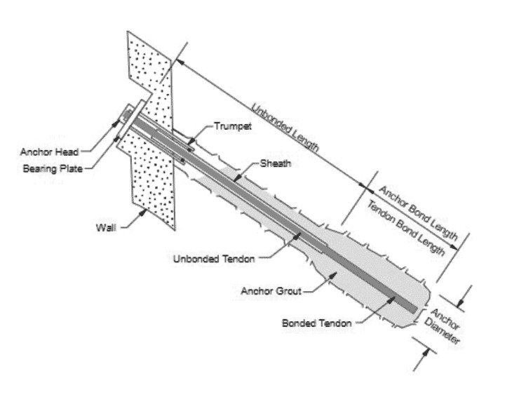
A conventional grouted ground anchor is a structural element installed in soil or rock that is used to transmit an applied tensile load into the ground. A ground anchor is installed within the bottom part of grout-filled drilled hole bonding a rod or one or more strands to the soil. The rod or strands are extended to the surface to form a tieback. The basic components of a grouted anchor consist of:
- Anchor head
- Free stressing (unbonded length)
- Bonded length
As will be discussed herein, the efficacy of ground anchors varies based on the anchor type, some of which are more effective than others in specific soil conditions. In this paper, two types of anchors are directly compared in terms of performance in loose to dense sandy soils.
Ground anchors
The schematic in Figure 1 shows the main components of a standard grouted ground anchor. As discussed by Sabatini et al., (1999), the following two main variations of the grouted ground anchor are commonly used across North America, with or without post grouting:
- Straight shaft gravity-grouted anchor
- Straight shaft pressure-grouted anchor
Expanded anchors by EBI
The concept of expanded anchor, also known as the Expander Body (EB), was first invented by the Swedish engineer Bo Skogberg during the 1980’s (Berggren et al., 1988) and later developed and evolved in Bolivia by Mario H. Terceros. The EB consists of a folded steel “balloon” that is installed at the tip of a deep foundation element (pile) or a tieback (Fellenius et al., 2018; Terceros and Terceros, 2015). The EB is installed in a bored pile/anchor and then injected with grout, producing an expanded element.
EB technology has been used successfully to increase the resistance of bored piles, anchors and tiebacks in different soils. The expansion process compacts the surrounding soil and increases the toe size, thereby increasing the resistance of the pile/anchor in bearing and tension. Many studies have documented the increased resistance of piles using EB (Herrera and Arce, 2016; Terceros A et al., 2022; Terceros and Terceros, 2015). The expansion of an EB unit is illustrated in the photographic sequence shown in Figure 2 (after Terceros et al., 2015).
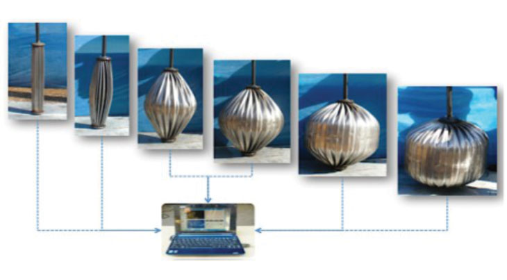
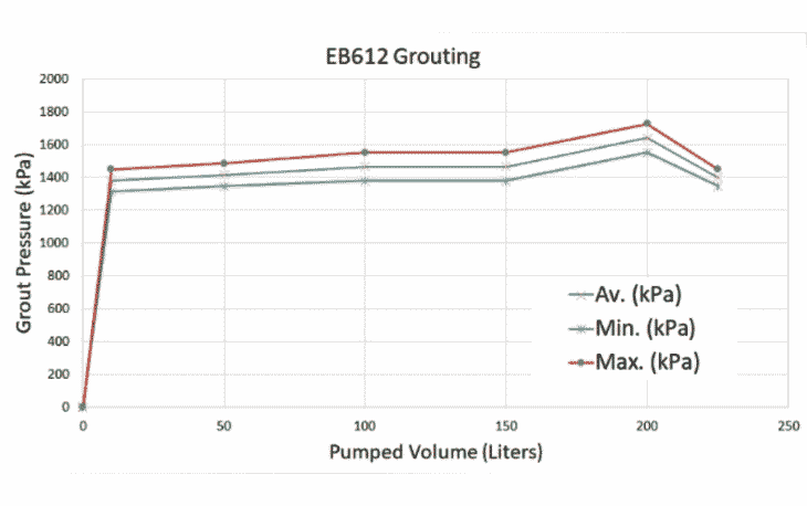
The grouting process of the liquid-tight EB takes place under controlled conditions while measuring the gradual increase in EB volume and required inflation pressure, which can be correlated to resistance. The applied grouting pressure reflects the soil resistance during expansion of the EB and is the measure of soil stiffness and strength at the time of inflation. The grouting record is obtained for each inflated EB and offers complete means of quality control (Terceros and Terceros, 2015).
Test program
A test program was conducted at a site in Ottawa, comparing the performance of a conventional tieback (strand anchor with gravity grouting) and a shorter tieback with an EB. The objective of the test program was to establish the most economical and feasible tiebacks to be used for a temporary support of excavation. It should be noted that the test was intended to verify the ultimate load (failure) of the tiebacks. All test anchors were less than five metres apart.
Subsurface conditions
The location of the test anchors was selected by the geotechnical engineer to be representative of the excavation site. Based on the borehole investigation and site observations, the following is a representative soil profile at the location of the anchor testing: Three metres of loose to compact silt and sand fill, followed by loose to compact silty sand extending to a depth of 12.5 m. Below lies a layer of very stiff silty clay with some sand extending to 17.8 m, followed by compact to very dense sand and gravel extending beyond 25 m depth (the depth of exploration). The groundwater table was encountered at a depth of 6.1 m.
EB technology has been used successfully to increase the resistance of bored piles, anchors and tiebacks in different soils.
Expanded anchor installation details
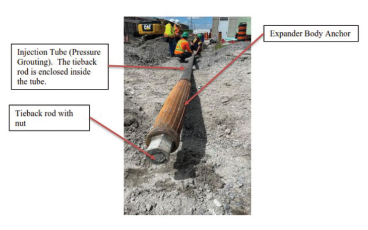
Two test anchors were donated by EBI and installed on June 20, 2022, by Marathon Underground Construction. One of the test EB units was sized for an 800 mm expanded diameter and 1.2 m initial length (EB812). The second test EB was sized for a 600 mm expanded diameter and 1.2 m initial length (EB612). The hole was drilled by reverse circulation with combined air and water injection. A 230 mm outside diameter (o.d.) temporary steel casing was pushed in place to a depth of seven metres, while the hole was drilled in loose to compact sand. The pre-assembled typical EB setup shown in Figure 3 was then lowered in the bored hole which was tremie-grouted around the EB assembly and the casing was withdrawn. The assembly above the EB anchor was wrapped with a polyethylene sheet to prevent bonding.
The EB assembly consisted of the EB anchor, a Williams 46 mm threaded tieback rod, Grade 150 kilopounds per square inch (ksi), and a 100 mm o.d. steel pipe welded to the top plate of the EB, which in this case would serve as the pressure grouting conduit in lieu of a flexible grouting hose. The rod was secured with a matching nut welded to the bottom EB plate and contained within the grouting pipe. The top 600 mm of the rod was wrapped in plastic sheathing for bond breaking. A steel cap with a mounted grouting assembly coupling was welded at the top of the grouting pipe which was about 500 mm above the top of the tieback rod to allow for upward movement of the rod during inflation of the EB body.
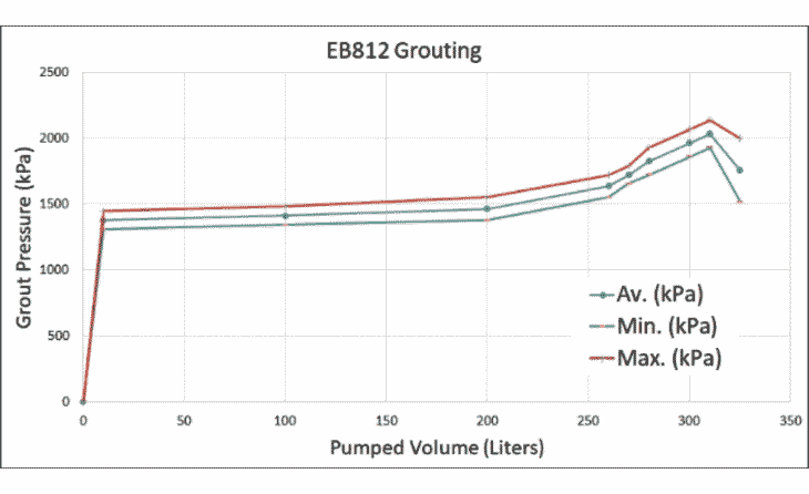
Four days after the initial installation, pressure grout was injected into the assemblies until the EB812 and EB612 anchors were fully inflated (about 350 and 225 litres, respectively). The grout pressure during pumping was plotted against the cumulative pumped grout volume as shown in Figure 4 (EB812) and 5 (EB612).
Conventional anchor installation details
Three gravity grouted test anchors were installed in May 2022, and two additional gravity grouted test anchors were installed in June 2022. Each anchor was installed with seven strands of 15-mm diameter, low relaxation and Grade 270 ksi, conforming to ASTM A416. Details of the anchor installation are provided in Table 1. Note that all anchors were grouted by tremie method. Only anchor TA04 was not post-grouted.
Table 1. Conventional 12-strand anchor details
| Test Anchor | Anchor diam. (mm) | Unbonded length (m) | Bonded length (m) | Total length (m) |
|---|---|---|---|---|
| TA01 | 150 | 12.5 | 9.0 | 21.5 |
| TA02 | 150 | 14.0 | 9.0 | 23.0 |
| TA03 | 150 | 14.0 | 9.0 | 23.0 |
| TA04 | 150 | 18.0 | 10.0 | 28.0 |
| TA05 | 250 | 18.0 | 10.0 | 28.0 |
Conventional anchor test results
All conventional anchors were tested by Marathon in accordance with the PTI DC35.1-14 recommendations. The design load (DL) in this case was specified at 720 kilonewtons (kN). Note that the tests were intended for cyclic loading (performance test); however, none of them reached the required test load of 1.33xDL as excessive movements were observed during the test. Tabulated and graphical results of all the five anchor tests are summarized in Table 2. The maximum test loads provided in Table 2 are the maximum sustained loads prior to failure.
Table 2. Conventional anchor test results
| Test Anchor | Maximum test load (kN) | Notes |
|---|---|---|
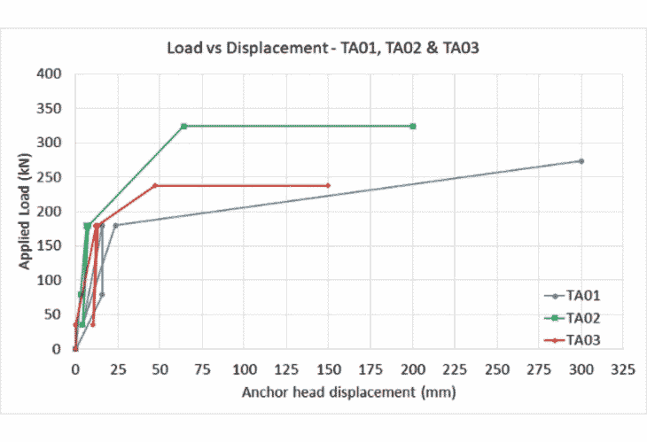
| TA01 | 150 | Anchor pulled out about 300 mm at 38% DL |
| TA02 | 150 | Anchor pulled out about 200 mm at 45%DL |
| TA03 | 150 | Anchor pulled out about 150 mm at 33%DL |
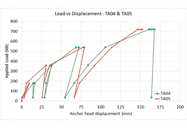
| TA04 | 150 | Cyclic loading conducted, creep failure at 75% DL |
| TA05 | 250 | Cyclic loading conducted, creep failure at 75% DL |
Graphical test results for Anchors TA01, TA02 and TA03 are shown in Figure 6.
Graphical test results for Anchors TA04 and TA05 are shown in Figure 7.
EB anchor test setup and details
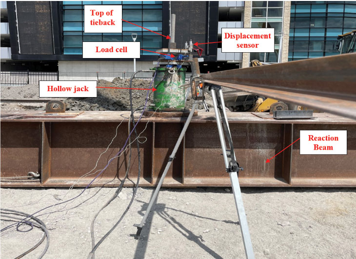
The anchors were designed and tested by Scientific Applied Concepts Limited. A reaction beam with centre access for the anchor rod projection was centred over the anchor location. A 300-ton hollow hydraulic cylinder and a 200-ton Geokon Model 3000 load cell were used to apply and measure the load. Two Novotechnik TRS electronic displacement transducers were used to monitor the vertical displacement of the anchor head at opposite ends of the top bearing plate. Displacement measurements were referenced to two tripods, one on each side of the reaction beam. Figure 8 shows a photo of the test setup at the anchor head.
EB anchor test procedure
While anchor testing is conventionally performed per the Post Tensioning Institute (PTI) guidelines, the EB anchors were tested to failure in accordance with ASTM Standard D3689-07 (2022), Procedure A for extended loading duration. The load increments were set based on a target test load of 1,400 kN, which is close to the yield strength of the rod. As such, 20 equal increments of 70 kN, each sustained for four minutes, until a failure load was reached. The anchor was then unloaded in five decrements.
EB anchor test results
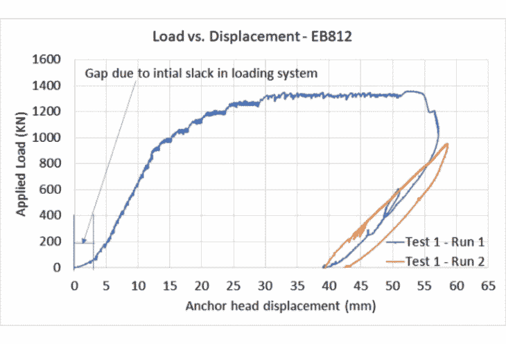
EB812
A practical load limit of the anchor was encountered at about 1,350 kN at which the load could not be sustained without continuous pumping. The measured load-movement data is shown in Figure 9. A second cycle of continuous loading to about 950 kN (PTI, 1.33 times DL) was initiated after unloading, showing no creep movement.
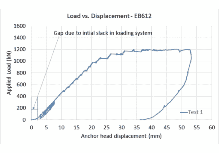
EB612
This anchor was loaded in 17 equal increments of 70 kN, each sustained for four minutes, until a total load of about 1,200 kN was reached, at which point higher loads could not be sustained. The measured load-movement data is shown in Figure 10.
Comparison of test results
As shown clearly from the test results, conventional anchors at this site showed a very soft response marked by excessive movement and substantial creep during early loading stages. While the deeper conventional anchors (TA04 and TA05) sustained somewhat higher loading than the shallower ones (TA01, TA02 and TA03). Post-grouting of the anchors did not seem to have any meaningful effect on anchor performance.
A direct comparison of the performance of the EB anchors versus the conventional anchors is difficult since the main criterion for anchor performance is stability. The conventional anchors pulled out prematurely and an accurate test of their stiffness (creep test) at lower loads was not possible since they rely mainly on friction which deteriorates with large displacement.
The performance of the expanded anchors was more robust throughout the test. A photo of the extracted test EB612 is shown in Figure 11.
The EB test anchors were purposefully installed in shallow loose to compact sands with the objective of improving the soils to a denser consistency around the anchors and achieving higher performance without deep drilling.
Furthermore, since a large portion of the EB anchor resistance is developed in pullout bearing, an increase in resistance with anchor movement can be expected as the bearing sands are further densified. Hence, the EB anchors can be expected to show larger stiffness when reloaded. As opposed to post grouting in conventional anchors, EB inflation is contained, and the grout bulb is near symmetrically shaped optimizing the anchor efficiency. In contrast, free post-grouting in loose sands is unpredictable and may find paths of least resistance to migrate away from the anchor system with little or no benefit to the performance of the anchor. This characteristic gives EB anchors a significant advantage in excavation support by reducing the risk of brittle pullout failures and fatigue from cyclic loading.
In conclusion, the EB anchors at this site showed three to five times the capacity of much deeper conventional anchors with substantial bonded length varying between eight and 10 m. These anchors have also been successfully used in marine clays where conventional anchors are practically not feasible. EBs are versatile and should be considered as a viable alternative in many difficult soil conditions.
Acknowledgements
The authors wish to extend their gratitude to Bengt H. Fellenius, Dr.Tech., P.Eng. for his valuable input and guidance.
References
- ASTM D3689-07, (2022) Standard Test Methods for Deep Foundation Elements Under Static Axial Tensile Load. ASTM International.
- Berggren, B., Sellgren, E., and Wetterling, S. (1988). Expanderkroppar. Anvisningar för dimensionering, utförande och kontroll (Expander Body. Instructions for design, installation and control). Swedish Commission on Pile Research, Report 79.
- Fellenius, B.H., Massarsch K.R., Terceros M.H., and Terceros, M.A., (2018). A study of the augmenting effect of equipping piles with an Expander Body. Proc. of DFI-EFFC International Conference on Deep Foundations and Ground Improvement, Rome, June 6–8, 2018, pp. 114–123.
- Sabatini, P. J., Pass, D. G. and Bachus, R C. (1999) “Ground anchors and anchored systems” Office of Bridge Technology, Federal Highways Administration, p. 4–15.
- Terceros, M. A., and Terceros, M. H. (2016). Recent Advances In The Expander Body Technology.
- Terceros M. H, and Terceros M. A. (2015). The use of the expander body with full displacement piles in medium dense sandy soils. Fourth Geo-China International Conference 2016, pp. 142–151.
- Terceros M.A., Terceros, M. H., and Marinucci, A. (2022) Foundation support and underpinning of an existing hotel with expander bodies to increase axial resistance. Australian Geomechanics Society, May 1–5, 2022, pp. 3387.