
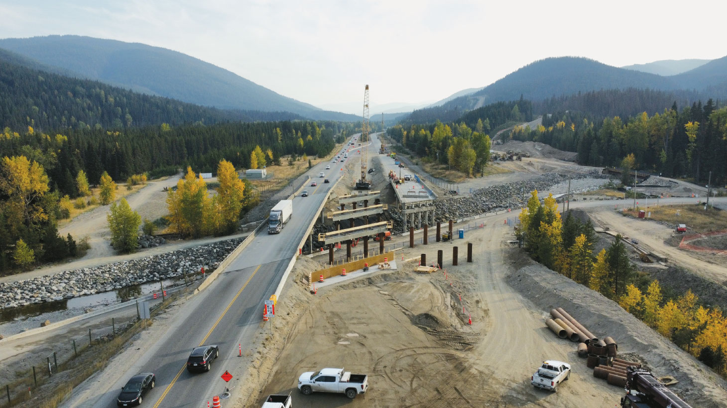
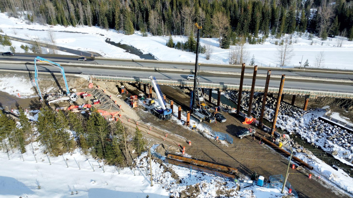
Extreme rainfall events in November 2021 caused major damage to the southern interior region of British Columbia. The atmospheric river event closed the Coquihalla Highway (Hwy. 5) and damaged several bridge structures. Juliet Bridge, located 50 km south of Merritt, B.C., previously consisted of twin 89-metre-long, three-span bridges. Juliet Bridge crosses Juliet Creek, a high-energy creek with boulders within the riverbed. During the event, Juliet Creek washed out the southbound south abutment and resulted in the collapse of one of the spans. The BC Highway Reinstatement Program was initiated to design and construct two new bridges, which were to be founded on deep foundations to prevent future events from undermining the structure.
Ground model
Site characterization beneath the existing Juliet Bridge was carried out to develop a ground model and evaluate the existing ground conditions. Due to the emergency nature of the work, site investigations were carried out immediately following the contract award in June 2022 with drilling equipment that could be sourced rapidly. Drilling investigations included conventional ODEX/mud rotary and Becker penetration drilling methods.
The soil stratigraphy beneath Juliet Bridge was evaluated using historic open-ended Becker drill boreholes with standard penetration tests from 1984. This was supplemented by a ground investigation in 2022, which comprised three instrumented closed-ended Becker (iBPT) boreholes (20 and 33 m) and one open-ended Becker borehole (25 m). Three ODEX/conventional mud rotary boreholes were drilled with in-situ SPTs to between 37.2 m and 39.6 m.
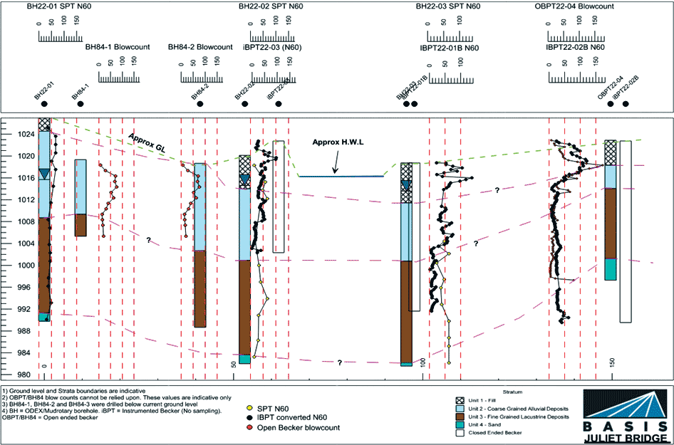
The geological ground model beneath Juliet Bridge consists of compact to very dense granular Fill (Unit 1) which is underlain by up to 16 m of coarse-grained dense to very dense Alluvial deposit (Unit 2). Underlying Unit 2 was an overconsolidated fine-grained Glaciolacustrine Silt (Unit 3), which had a thickness of up to 18 m. The silt comprised alternating layers of brown and grey laminated silts with a stiff to hard consistency. Underlying Unit 3 is Unit 4, which was a compact to very dense sand with variable silt and gravel content.
This entire unit thickness was not proven due to limited drilling casing and time. Glacial till was not encountered in the boreholes; however, a seismic line was performed by Worley Parsons (July 2013) for BGC (2015) in support of the Trans Mountain Pipeline Expansion in the vicinity of Juliet Bridge. P-Wave velocities greater than 2,303 m/s were encountered. This was interpreted as being glacial till and approximately 15 m below the deepest 2022 borehole. Groundwater levels were observed to range between 5.18 m and 11.28 m depth.
The moisture content of the fine-grained silt ranged between 21 and 26.2 per cent, and the plasticity index (PI) was approximately seven per cent. As such, these soils can generally be characterized as low plastic soil. The silt content ranged between 69 and 97 per cent, and therefore were of low permeability.
Due to the silt being low plastic and having a low permeability, consideration was given to treating the deposit as both a frictional material and a cohesive material. Based on a PI of seven per cent, a drained friction angle of 25 degrees (using Terzaghi et al. 1996) was assumed for this material. This is also consistent with the SPT N60 blow counts of 30 to 50 blows/0.305 m. Terzaghi et al. (1996) was also used for correlation of PI and undrained shear strength (su) ratio. Based on a PI of seven per cent, the ratio of Su/N60 of six is appropriate. Based on an N60 range of 30 to 50 blows/0.305 m, an undrained shear strength of 200 kPa was adopted.
The 2022 investigation showed good correlation between the SPT N60 values from in-situ borehole SPT tests and equivalent SPT N60 values interpreted from iBPT’s in Unit 2 but not Unit 3 (fine-grained lacustrine deposit). For Unit 3, the iBPT showed an underestimated blow count. This was attributed to the induced pore pressure generation and reduction in effective stress below the iBPT tip during drilling.
Although the equivalent iBPT N60 values in the fine-grained deposits were underestimated, the iBPT indicated the complexity of the lacustrine silt and suggested the fine-grained soil would be problematic for pile design and pile driving. The iBPT blow counts provided foresight that the pile shaft strength would require a setup period and initial unfactored ultimate resistances would be lower than expected at the end of initial drive (EOID) versus the long term. The unknown was surrounding the actual setup period of the silt and whether this would fit into construction timelines.
Pile design
The Juliet Bridge consisted of a northbound and southbound bridge. For each bridge, the pile configuration comprised four 914 mm diameter piles spaced at 1.6 m across three piers and two abutments. The design methodology for calculating the pile ultimate resistance was based on an open-ended driven steel pile with 19 mm wall thickness. The pile driving shoe was designed such that it had the same outside diameter as the casing.
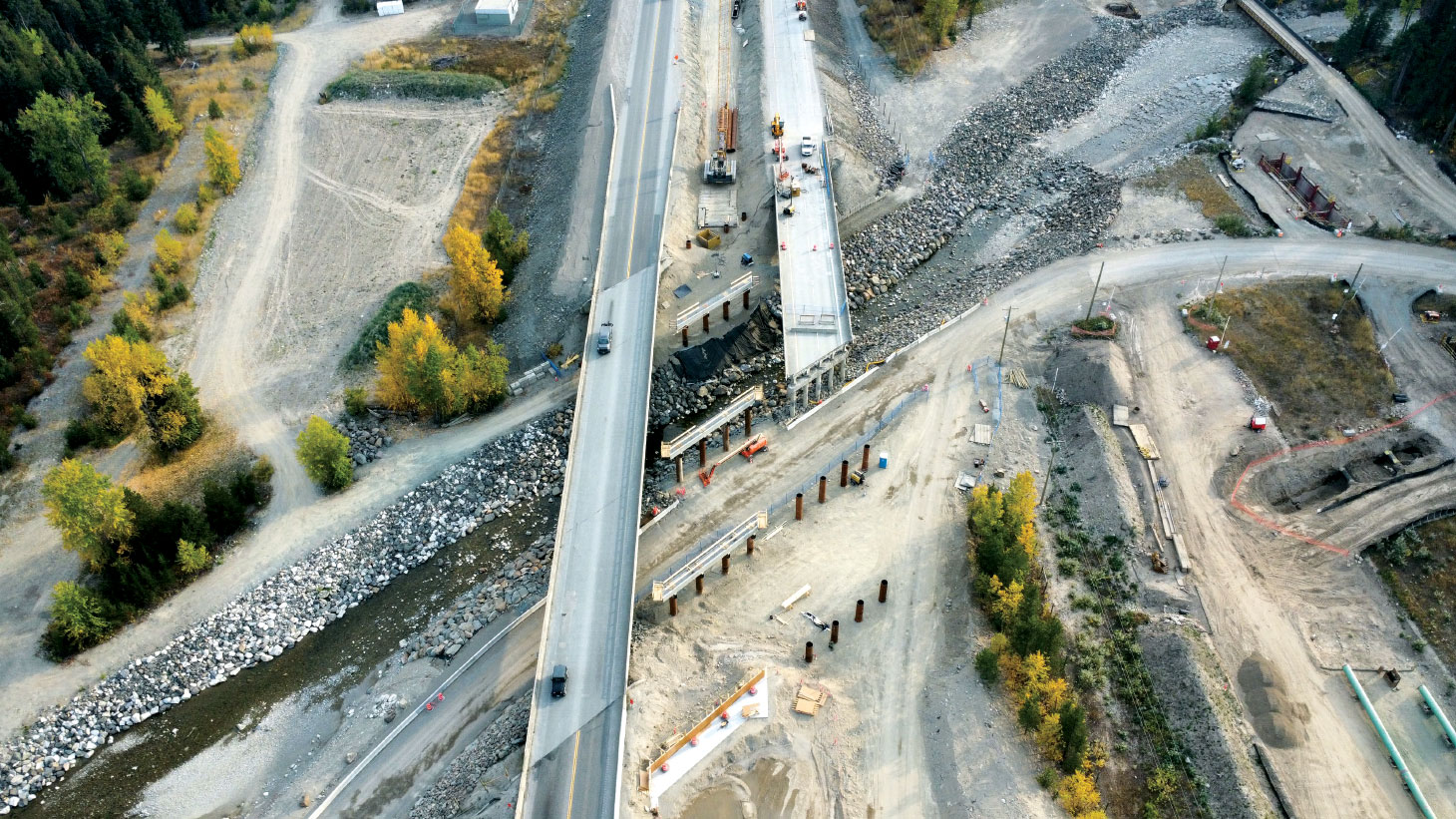
Due to the emergency nature of the project and the tight construction schedule, the pier caps and superstructure on the northbound bridge needed to be installed immediately
A sensitivity analysis between undrained strength (alpha, α) methods and effective stress (beta, β) methods was performed when determining the geotechnical ultimate capacities. Using the alpha method and adopting 200 kPa for the silt, the pile design yielded less conservation ultimate capacities than the beta method using a pile/soil friction angle of 25 degrees. Given the undrained shear strength of this material was based off the Terzaghi et al (1996) correlation rather than laboratory testing or cone penetrometer testing, a more conservative approach was taken of adopting the beta method following the guidelines in API (2011). The maximum factored axial loads for each pile at Juliet Bridge was 2,500 kN at the abutments; 3,700 kN at Piers 1 and 2; and 3,500 kN at Pier 3. The calculated ultimate resistances from the beta analysis were factored based on guidance from CAN/CSA-S6-19. The resistance factor of 0.45 was used for piles in compression.
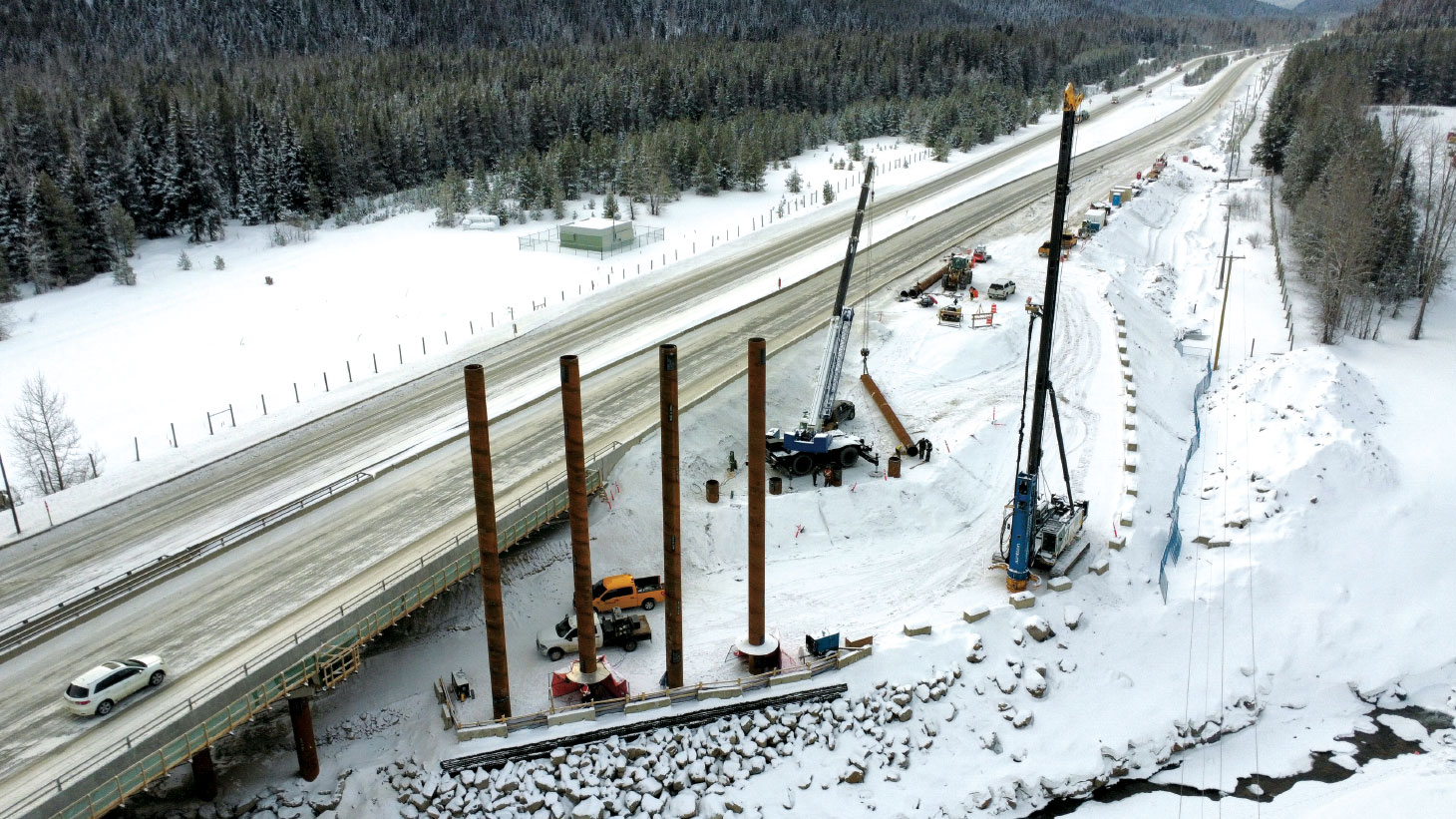
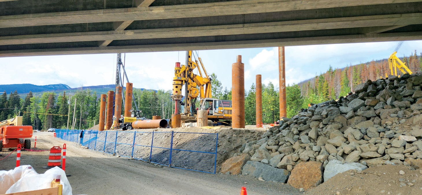
The piles at the south abutment Pier 1 and Pier 2 were in proximity to the Juliet Creek rip rap and were pre-drilled such that the rip rap would not adversely impact pile driving/damage the driving shoe.
Moreover, future scour depths were taken into consideration and shaft resistances that may have been developed in the first four to 10 m of the pile were ignored.
The applied 0.45 resistance factor was based on a WEAP, satisfying the B.C. supplement to CAN/CSA-S6-19 criteria for “high degree of understanding.” Therefore, an EOID pile termination criteria was determined based on the desired static axial ultimate pile resistances. The WEAP set criteria was based on blows per metre at specific driving stress and stroke heights. As a confirmatory tool as well as to potentially increase the resistance factor applied to the unfactored ultimate resistance, PDA tests were proposed to be performed at a minimum of one pile at each pier and abutment location.
Results from pile driving
Due to Juliet Bridge construction being on an expedited/emergency schedule, several hammers were used on the project. At the southbound bridge piers and abutments, a Junttan HHK12S hydraulic hammer was selected. This was also the hammer used on the northbound bridge except for the south abutment and Pier 1, which used an APE D-138 and D-62 hammer. The results discussed in this section only evaluate data from the HHK12S hammer and does not include the PDA tests performed where piles refused in glacial till.
Pile driving commenced at the northbound bridge in August 2022 at Pier 3. The pile tip design length was 35 m. The WEAP set criteria for achieving a target ultimate resistance of 8,071 kN was 151 blows per metre with a maximum stroke of 1.5 m or 170 kNm driving stress. At design tip, the four piles had blow counts ranging from 48 to 80 blows per metre with driving stresses less than 130 kNm. The first pile in the pier had the highest blow counts with the subsequent piles having lower blows per meter. It was apparent that not only did the piles not achieve the WEAP criteria but at 1.6 m pile spacing, the pore pressure generated at the first driven pile was affecting subsequent piles.
Based on the lower blow counts, the shaft resistance at EOID was considerably less than expected. Moreover, it was apparent that piles in the lacustrine silt were performing in a similar manner to the lower iBPT N60 results. At this stage, the setup of the silt was unknown and therefore a PDA on pile PN14 was performed at EOID and three days after EOID. Ultimate resistances of 3,400 kN and 4,100 kN were calculated at EOID and three days, respectively. This demonstrated that the ultimate capacities were significantly lower than the target ultimate resistance (8,071 kN) at three days. The PDA results showed a 20 per cent increase in capacity after three days.
The unknown was surrounding the actual setup period of the silt and whether this would fit into construction timelines.
Due to the emergency nature of the project and the tight construction schedule, the pier caps and superstructure on the northbound bridge needed to be installed immediately. As a result, there was no opportunity to wait and see if the piles setup to the design resistance over a longer setup period.
Therefore, to achieve the design resistance within the required schedule, the piles at the piers were driven deeper to glacial till such that the pile resistance could be demonstrated immediately following pile driving based on the WEAP criteria. At the abutments, the piles were driven deeper than design. However, due to the lower structural demands, the WEAP set criteria and ultimate capacities were met above the glacial till.
The southbound bridge had a slower construction schedule and there was the opportunity to test the longer-term setup effects of these piles. A re-strike with PDA test was carried out on pile PS18 5 days and 142 days after EOID.
Analysis and discussion
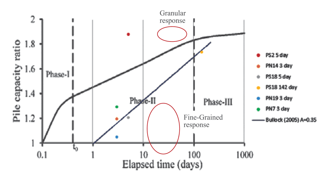
The setup of the lacustrine silt was examined at five piles at Juliet Bridge using the hydraulic hammer. Short-term three and five-day increases in shaft resistance were estimated to be between 1.06x and 1.89x, with the average being 1.33x. A PDA was performed on PS18 142 days after EOID and there was an increase in shaft resistance of 1.74x. For the same PDA test, the shaft pile capacity increased by 1.44x after 137 days (post five-day restrike).
Komurka et al, 2003, defined a curve of elapsed time versus pile capacity ratio with the pile capacity ratios for five piles at Juliet Bride being plotted. It is suspected that given the fine-grained nature of the silt at Juliet Bridge, pore water pressures during pile driving would have developed quickly and dissipated slowly. This is due to there being a high percentage of fines and therefore the silt having a low permeability. As a result, most of the pile setup at this site is likely to be associated with Phase II and have a linear relationship.
The project would have benefited from at least one deep borehole that proved the depth and properties of the glacial till.
PS02 shows a considerably higher setup and increase in shaft resistance (1.89x) after five days than the other piles. It is possible that this is because this pier is in a zone of higher proportions of granular soils. This is supported by BH22-01 lab testing, which indicates the silt is 17 m thick with 9 m having 97 per cent fines and 8 m having 68 per cent fines. Therefore, the driving-induced excess pore water pressures would have dissipated faster due to the higher permeability soil. PN14 to PN19 and PS18 appear to be well grouped with ratios between 1.06 and 1.44, where the proportions of fine-grained materials are likely to be higher.
The following conclusions were drawn from the pile design and installation experience at the Juliet Bridge:
- Sawant et al, 2015, discussed that when a pile is driven into the ground, the soil around the pile shaft is displaced predominately in radial direction and the soils around generate pore water pressures, ultimately decreasing the effective stress. This effect was observed in both the pile driving and iBPT drilling. Furthermore, even at 1.6 m spacing, the disturbance during each pile drive was experienced by neighboring piles.
- Significant pore pressure can develop during pile driving in low plastic silts. This pore pressure dissipation is more “clay like” and setup effects can take a significant amount of time. Although time did not permit on this project, further investigation of the silt would have been valuable – specifically, CPT testing with dissipation tests for insight into the permeability and rate of pore pressure dissipation.
- If the construction schedule is constrained and pile resistance needs to be achieved immediately following installation, it is a good idea to have an alternate option. In this case, driving deeper to the glacial till horizon was carried out. The project would have benefited from at least one deep borehole that proved the depth and properties of the glacial till.
- The SPTs provided reasonable information on the long-term parameters of the soils. The lower equivalent SPT values from the iBPT were weighted lower when considering the geotechnical resistance. It turns out that the iBPTs are a reasonable indication of the EOID resistance that could be expected prior to pile setup.
- Glaciolacustrine sediments commonly occur in southern British Columbia. As an industry, collaboration of pile driving data in these silts would help to better define setup periods and predict these silts performances. As a result, this would help optimize future pile designs and lead to significant construction savings.

Stuart Childs is an engineering geologist with more than 10 years’ experience across Canada, UK and Africa. The author would personally like to thank his mentor, James Williams, as well as Kiewit and Henry Drilling for support during design and construction. Finally, he would like to thank the Ministry of Transport and Infrastructure for performing PDA testing and their support during pile installation.