
For decades, the construction industry has relied on indirect methods to assess the quality of drilled shafts. Drilling logs, concrete volumes and integrity testing have long been the standard toolkit. But a growing body of evidence suggests these methods leave a troubling blind spot as they often cannot tell engineers what the shaft actually looks like underground.
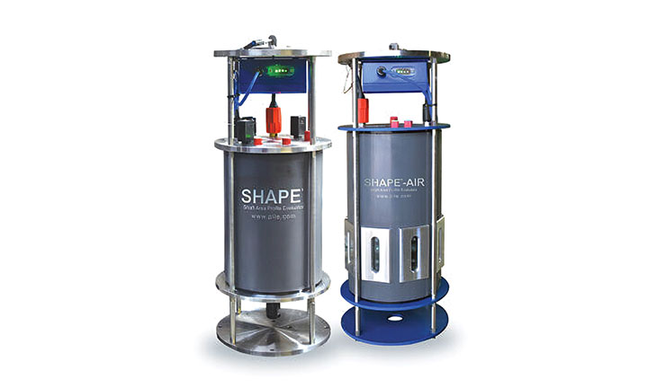
Pile Dynamics, Inc. (PDI) developed the Shaft Area Profile Evaluator (SHAPE) to address exactly that gap. The tool provides a continuous, 3D picture of a drilled shaft’s as-built geometry and verticality, giving engineers and contractors direct measurement data where indirect inference used to be the only option.
The problem beneath the surface
Drilled shaft construction is inherently complex. Soil conditions change with depth. Drilling tools can deflect. Unstabilized borehole walls can collapse or deform. The result is that the shaft as designed and the shaft as built are not always the same thing.
“The most common irregularities in drilled shafts are necking, bulging, inclusions and deviations from verticality, often caused by soil instability and changing soil conditions,” said Wayne Dalton, P.E., director of product development and engineering at PDI. “Out of verticality typically occurs due to variable ground conditions, tool deflection or improper alignment, introducing uncertainty in capacity and durability by affecting load alignment.”
These are not minor cosmetic concerns. A shaft that deviates from vertical, even subtly, can introduce eccentric loading that the original design never accounted for. Necking reduces cross-sectional area and therefore load capacity. Inclusions compromise structural integrity. Yet for most of the industry’s history, these issues have gone largely undetected until a problem emerges.
“Irregularities often go undetected because conventional QA/QC methods rely on indirect data such as drilling logs, concrete volumes or integrity testing,” Dalton said. “These approaches typically do not capture deviations from verticality or full geometry, leaving alignment issues unquantified.” The consequences, he says, are frequently underestimated by contractors in the field. “Poor shaft geometry or misalignment can lead to reduced capacity, unintended eccentric loading and increased stresses that are not accounted for in design. These issues often result in unexpected performance problems, costly remediation or delays.”
How SHAPE works
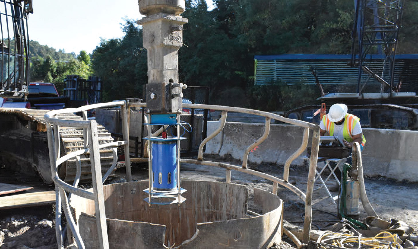
SHAPE is deployed into the drilled shaft after drilling is complete and before concrete is placed, a critical window when the geometry of the borehole can still be measured and any issues addressed. The tool uses a combination of measurement technologies to build a complete picture of the shaft.
“SHAPE is deployed in the shaft and uses differential pressure to determine depth, ultrasonic transducers to measure radius along the shaft and ultrasonics to continuously measure the wave speed to ensure accuracy along the entire length of the shaft,” Dalton said. “These measurements provide a full 3D representation of the as-built shaft, enabling engineers to validate geometry, alignment and capacity assumptions against actual conditions.”
A key differentiator from conventional sonic caliper tools is the continuous nature of SHAPE’s measurements. Traditional tools require the operator to stop at discrete elevations to take readings, a process that is time-consuming and leaves data gaps between measurement points. SHAPE collects data continuously during deployment, eliminating those gaps.
“Relying on outdated or incomplete inspection methods means accepting uncertainty in what was actually built, particularly in terms of geometry and alignment. That uncertainty can lead to hidden defects, reduced performance and increased risk of costly remediation or long-term issues.”
Wayne Dalton, Pile Dynamics, Inc.
“SHAPE provides continuous measurements along the full shaft during deployment, eliminating the need to stop at discrete elevations and enabling a faster, more accurate 3D representation of both geometry and verticality,” Dalton said. “This approach, combined with real-time ultrasonic wave speed compensation for fluid density changes, improves accuracy while reducing time on site, helping contractors save both time and cost.”
The real-time wave speed compensation is particularly important on active jobsites, where drilling fluid properties can vary with depth and temperature. By continuously calibrating for these changes, SHAPE maintains accuracy even in variable borehole conditions.
Reading the results
The output from a SHAPE inspection is designed to be actionable, not just informational. The system generates a comprehensive report showing shaft profiles from all cardinal directions, along with critical dimensions, verticality data and bearing information. “This enables engineers to evaluate as-built geometry, directional alignment and impacts on load transfer and performance,” Dalton said.
The data can also be integrated with project records and design models, supporting a more comprehensive digital construction workflow. “SHAPE fits into a digital construction workflow by providing high-quality, as-built foundation data that can be integrated with project records and design models,” he added. “This enables a more data-driven approach where engineers and contractors can validate construction in real time and maintain a traceable record of foundation performance.”
Integration into the field workflow
One of the practical challenges with any new inspection technology is adoption, specifically, how easily it fits into an existing construction operation without adding cost, complexity or schedule risk. PDI designed SHAPE with this in mind. The tool can be attached to the drill string or deployed independently using a battery-powered winch, giving field crews flexibility depending on site conditions and equipment availability.
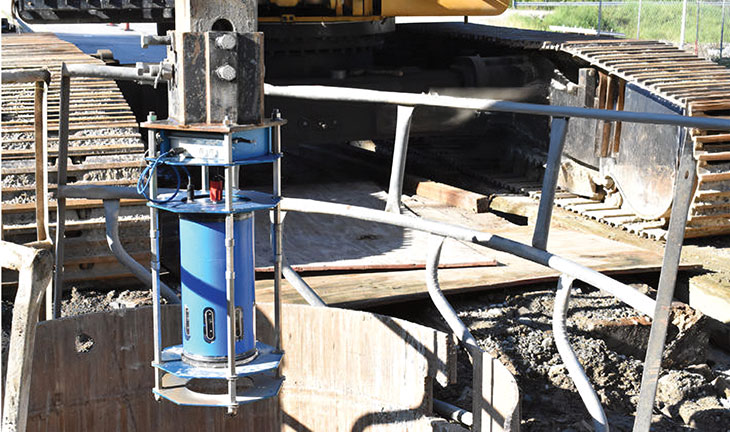
“SHAPE is designed to integrate seamlessly into existing workflows, requiring minimal additional setup and fitting naturally between drilling and concrete placement,” Dalton said. “Its flexible deployment allows it to be quickly attached to the drill string or deployed with a battery-powered winch, providing valuable data without disrupting production or impacting schedule.”
The learning curve for field personnel is also intentionally low. Basic training is sufficient for deployment and data collection, and the processed outputs are structured so engineers can efficiently evaluate geometry and alignment without extensive post-processing.
A case for routine use
Perhaps the most important message PDI wants to convey is about when SHAPE should be used – not just on test shafts or when problems are suspected, but as a standard part of every drilled shaft installation. “Contractors should use SHAPE immediately after drilling and before concrete placement, and ideally as a standard practice throughout all stages of drilled shaft installation, not just on test shafts,” Dalton said. “This approach enables early and consistent identification of issues, helping reduce risk, minimize rework and improve over all project outcomes.”
Dalton says that the industry’s tolerance for uncertainty in foundation quality carries real risk – risk that is often invisible until it becomes expensive.
“Relying on outdated or incomplete inspection methods means accepting uncertainty in what was actually built, particularly in terms of geometry and alignment,” he said. “That uncertainty can lead to hidden defects, reduced performance and increased risk of costly remediation or long term issues. Quality control should focus on verifying the as-built condition, including both geometry and verticality, rather than relying solely on indirect indicators. Direct measurement is critical to reducing uncertainty and validating design assumptions.”