

leddamarita/123rf
Micropiles can be considered an alternative to mass concrete and large monopile foundations. Micropile foundation systems are constructible in different ground conditions without changing the equipment or the installation method. Moreover, only small drilling equipment is required.
It is particularly desirable to have a deep foundation with a smaller footprint for wind turbine towers. To resist the imposed overturning moments, the use of the patented Post-Tensioned Micropiles (PTMP) in compression and tension with Groutable Void Forms (GVFs) relies on activating the soil mass under the foundation (see Figure 1). This reduces the size and depth of the now pre-tested foundation, resulting in large steel pipe piles, reinforcing steel and concrete savings.
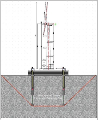
Figure 1: Activation of soil mass
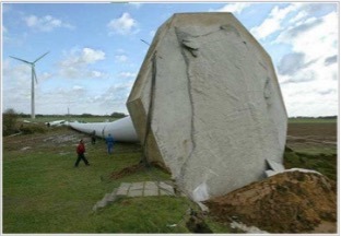
Figure 2: Overturning failure caused by massive rainstorm
Three possible post-tensioning scenarios for micropile foundations
A no-void case, where the micropile is in direct contact with the foundation cap, prevents the micropile from mobilizing skin friction forces between the grout and soil. The post-tensioning force (PT force) in a pile becomes compressive stress at the pile-to-cap interface. An actual pile test is only possible if each pile is tested before the foundation is placed and locked off later on top of the finished foundation.
On the other hand, in an unfilled compressible void, where a gap between the micropile and foundation cap for tensioning remains unfilled, it allows unrestrained movement between the top of the pile and the bottom of the cap. Since the void remains unfilled, long-term consolidation and settlement are possible if founded on the soil. However, it can be used if founded on a rock. In this case, it is not a pile, but an anchor in tension. The rock supports the compression loads.
Lastly, in the patented GVF system for foundations on soil, the void between the micropile and foundation cap is filled with cement grout after tensioning. It allows unrestrained pile movement between the micropile top and the bottom of the cap during tensioning. After filling the void with cement grout, compressive forces and tension forces can be transmitted.
The technical benefits of using the GVF system include no movements of the foundation and pile occurring, unless externally applied forces are larger than the applied PT forces in tension or compression.
Figure 3: Load transfer diagram
Standard foundations
Foundations for wind turbines and transmission lines typically consist of large reinforced concrete spread footings. If founded on soils, the compression loads are only supported by the soil and the overturning loads are resisted by the counterweight provided by the concrete foundation. However, changes in loading from compression to uplift can cause a fatigue problem, which is difficult to predetermine. Thus, wind turbines may overturn (see Figure 2).
For foundations on soil, an alternative post-tensioned foundation system was developed using micropiles supporting a smaller foundation pile cap. Not only will this micropile system minimize or eliminate the fatigue problem, but it can also provide up to a 75 per cent reduction in the foundation area. Moreover, it reduces concrete consumption by 40 per cent and reduces reinforcing steel by 70 per cent, resulting in a total foundation cost savings of about 25 per cent.
Foundation design objectives
The following design objectives should be achieved to provide a post-tensioned micropile foundation system, such as for wind turbine foundations:
- Design and construct PTMP to achieve a design load in compression and tension with the required safety factor.
- Provide a rigid foundation to resist extreme overturning moments while limiting the pile cap size.
- Improve rotational stiffness and reduce/eliminate foundation movement through post-tensioning.
- Reduce excavation and backfill required for the pile cap/tower foundation.
- Only small drilling equipment is required.
- Reduce concrete and steel reinforcing consumption to optimize foundation efficiency and performance.
- Provide a cost-effective post-tensioned deep foundation system.
The GVF temporarily separates the pile from the pile cap during stressing and testing to a load higher than the design load in compression and tension while allowing some range of pile movement. After post-tensioning, the GVF is filled with cement grout to transfer compression loads to the pile.
In the patented GVF system for foundations on soil, the void between the micropile and foundation cap is filled with cement grout after tensioning. It allows unrestrained pile movement between the micropile top and the bottom of the cap during tensioning.
Prime advantages
The post-tensioning procedure using GVFs with micropiles controls foundation settlement and prevents overloading the soil (bearing capacity failure) with a prescribed sequence of post-tensioning. It also allows for post-tensioning in balanced anchor groups and permits gradual load transfer into the piles without overstressing the soil.
Moreover, settlement of the foundation cap is minimized as the piles take over the compression load from the cap, and fatigue failures can be eliminated since the post-tensioned tension and compression loads are higher than the design loads and, as such, minimize or eliminate movements during load changes (see Figure 3). Finally, the reduction of concrete and steel also reduces the environmental impact.
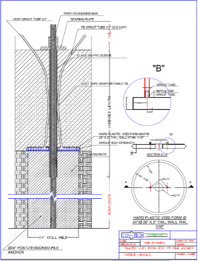
Figure 4: Location of the GVF with grout tubes
Two construction methods
It is possible to use GVF with two different construction methods. In the first method, micropiles are installed before the concrete foundation cap is placed. The second is to install micropiles after the concrete foundation cap has been placed and the micropiles are drilled through pre-installed sleeves inside the pile cap.
The advantage of the first method is that a larger drill hole diameter can be achieved using the open or cased hole drilling method, and that the GVF can be wet set into the upper cement grout body of the pile (see Figure 4). Three types of post-tensioning steel tendons may be used:
- Seven wire, 270 kilopound per square inch (KSI) low relaxation strand;
- Solid, 150 KSI high-strength bars; or
- Grout injection bored hollow bars.
Strand and solid bars are used primarily for micropiles drilled through soil into rock, or for foundations on soil when a larger drill hole is required and the micropiles are pre-drilled.
For example, a 1.6-milliwatt wind turbine foundation was constructed in Tehachapi, Calif., using 300-millimetre-diameter pre-drilled PTMPs and GVFs. The 100-metre-tall lattice tower was founded on five individual pile caps, each supported by four micropiles. The PTMP/GVF system was load tested to ensure that the micropile system’s construction cost and long-term maintenance could be reduced.
Larger diameter holes were drilled before the construction of the pile cap. Next, the solid micropile bar was grouted, and the GVFs were wet set on top of the micropile grout and in the levelling pad with pipe sleeves and grout tubes. After placing the rebar cages, the pile caps’ concrete was placed. All five pile caps are cast on four micropiles, with a total of 20 micropiles. The micropiles are stressed in sequence after placing the bearing plates and nuts. Next, the grout is pumped through one tube and vented out of the other to ensure 100 per cent filling of the GVF with grout. After that, the micropiles can transfer the applied compression and tension loads into the ground.
The advantage of the second method is that the micropiles are drilled through pre-formed sleeved holes in the foundation cap fitted with a pre-installed GVF under the foundation cap. However, the disadvantage is that the drill hole size is determined by the smaller sleeve inside the foundation slab, which does not provide sufficient cement grout under the GVF.
The size of the bearing plate dictates the smaller sleeve size in the foundation slab. However, the issue with the grout under the GVF is not present when using the grout injection bored method with hollow bars. In this case, the cement grout is injected simultaneously during the drilling operation. The drill bit has small diameter side holes through which the grout will exit under high pressure, such as during jet grouting. This will flush out the soil and create a larger drill hole under the GVF. This method also greatly improves the condition of the ground around the micropile and, therefore, creates a higher skin friction capacity.
Simultaneously stressing the micropiles in pairs will pre-stress the piles and post-tension the foundation before the GVF is filled with cement grout. The number of micropiles stressed in pairs is dictated by the compression load capacity of the soil. When this load is reached, the GVFs are grouted. After the grout has gained sufficient strength, the final stressing procedure can continue.
The post-tensioning procedure using GVFs with micropiles controls foundation settlement and prevents overloading the soil (bearing capacity failure) with a prescribed sequence of post-tensioning.
Safety of wind turbine and transmission line foundations improve
Compared to a large-diameter mass concrete foundation, the micropile/GVF foundation system reduces the foundation area by more than 75 per cent, reduces concrete consumption by more than 40 per cent and reduces reinforcing steel consumption by more than 70 per cent. The system also reduces the preliminary estimated total foundation cost by 20 to 30 per cent.
As a result, the safety of wind turbine and transmission line foundations composed of post-tensioned micropiles with GVFs is improved, and the cost is significantly reduced. Therefore, the micropile/GVF system on soil, provides a competitive and safe alternative to large reinforced concrete and large mono-pipe pile foundations on the soil.
Photos courtesy of Horst Aschenbroich